COMPUTERIZED DUCT DESIGN©
by Bill Smith, president of Elite Software

 The optimal layout and sizing of duct systems has become more and more a concern for hvac system designers. Although most duct systems are designed either by an hvac contractor or a consulting engineer, many plant designers often find it necessary to alter a duct system design to correct obvious flaws. Not only are duct system modifications made to clear obstructions, they are sometimes made for obvious economic reasons. The original design may include costly, unnecessary transitions and special fittings. An experienced sheet metal person can quickly spot these anomalies in a duct design. However, modifications to a duct design must be made carefully to insure that the system will work as intended. Whether performing initial design or modifying someone else's design, it is a good idea to analyze proposed duct systems with computer software to ensure that they will work properly.
There are two basic aspects of duct design: duct layout 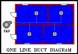 and duct sizing. The strategic placement of the fan and the optimal routing of ductwork helps to create a system that is both economical and easily balanced. However, system layout is a task that requires experience and engineering judgment. At present, the layout stage of duct design cannot be aided much by the computer. The best that software can do in these situations is to help the designer perform interference checks. To make automatic interference checking possible, a complete CAD (computer aided drafting) system is required.
However, the sizing aspect of duct design can be greatly aided with simple, low cost computer software. Just as with intelligent system layout, the proper sizing of duct sections helps to keep a duct system low cost and naturally balanced. Since the layout of a duct system is so often dictated by the architecture of a building, a designer usually has more latitude concerning the sizes of each duct section. Of course, small ceiling spaces and other obstacles sometimes restrict what duct sizes can be used.
Most hvac contractors and sheet metal shops have traditionally used a "wheel" nomograph from the Trane Company called a Ductulator for duct sizing. This device uses the equal friction method for sizing and shows the designer both required round duct diameters and equivalent rectangular sizes. It is very fast and easy to use, and designers have relied on it for years.
As good as a ductulator is, duct sizing software goes beyond a ductulator in several ways. Software typically allows the designer to use other methods of sizing such as static regain, total pressure, and constant velocity which may be more appropriate for certain situations. Other advantages include the ability to print a bill of materials with material and labor costs, perform an acoustic analysis, and interface to a CAD system.
Most duct programs are geared towards sizing new duct systems only, but some can analyze existing systems where the sizes are already set. When trouble shooting a problem job, it is nice to have a program that can simulate the duct system as installed and show velocities and pressures available at all points in the system. In this way, possible solutions to a problem can be tested with the program before any physical modifications are made.
One other advantage to using a duct program that can analyze pre-sized systems is that it can also be used as an estimating program as well. If duct sizes and lengths are entered as per the plans, then the designer can select to print a bill of materials with all associated costs. Although not as detailed as a specific duct estimating program, some of the duct sizing programs can be reasonably used as estimating programs.
The only drawback to using duct sizing software is that the designer has to type in more data about the duct system than he may be used to dealing with manually. For example, when manually calculating duct sizes, a designer just looks at a duct section on a plan, determines what cfm it carries, and then spins a ductulator or punches a few buttons on a calculator. When using a program, the designer must number each duct section, specify the upstream duct sections, enter the duct lengths, specify where fittings occur, and enter the discharge cfm for each runout duct. In addition, data concerning duct height and width constraints, R-value of duct insulation, duct material, fan data, and other such data must be entered. All of this input does take time, but most designers find it worth the effort because of all the report features available.
Fortunately, most duct sizing programs have a full screen entry system that provides an easy to use "fill in the blank" style of input. In addition, on-line help information is typically available for any input item by pressing a help key. Such nice input procedures really make entering all the necessary data a tolerable task.
Even faster than a full screen entry system, is the ability to take data from a CAD drawing and pass it directly into a duct sizing program. CAD systems allow the designer to make a quick one-line sketch of the duct system that shows the scale length of each duct section and how they are connected. Next, the CAD software passes the data to the duct sizing program which then sizes the duct system and prints reports. The CAD software reads the computed duct sizes and then automatically creates a double line drawing showing the correct duct sizes, fittings, and duct shape (round, rectangular, flat oval).
Integrated drafting and design is a tremendous time saver because the manual typing of data is greatly reduced. In addition, a great deal of drafting is performed automatically as the CAD software can automatically convert single line duct diagrams into complete double line duct drawings. Precision accuracy and automatic dimensioning are other nice benefits of automated duct drafting. Any hvac contractor or sheet metal shop that must routinely provide as-built drawings would do well to look into integrated CAD and duct design packages.
It is interesting to note that the vast majority of duct sizing software suppliers have chosen AutoCAD as the basic CAD package to work with. One of the main reasons that AutoCAD is so popular is that it provides a graphic programming language called AutoLISP that facilitates the integration of design programs such as duct sizing.
Whether combined with CAD or not, duct sizing software offers significant advantages over manual duct size calculations. What's more, all late version software has become very easy to use. With dropping hardware and software prices, anybody involved with duct system design or fabrication can benefit from computerized duct analysis.
Mr. Smith welcomes your email about this article. - email
Copyright ©
Elite Software Development, Inc., webmaster@elitesoft.com