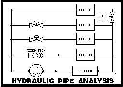
Chilled and Hot Water Pipe Analysis

HSYM PROGRAM OVERVIEW

The Elite Software HSYM program analyzes centralized HVAC piping systems that use chilled and/or hot water. In the simulation of HVAC water piping systems, HSYM can determine pressure losses, actual operating pressures, temperatures of air and water, flow rates, and obtainable unit loads throughout the system. Complex systems containing all types and sizes of pipe, insulation, boilers, chillers, pumps, coils, exchangers, 2 and 3 way control valves, water temperature control valves, radiators, and insulation can be defined. HSYM is not designed to size pipe or select equipment as are many other less sophisticated programs. Rather HSYM is designed to simulate the operation of an HVAC water as a whole. HSYM provides a cost effective way to obtain a steady state analysis of an existing or a proposed system. With HSYM a designer can investigate a myriad of design alternatives in seacrh of an optimal design that provides low cost and reliable performance. Besides sophisticated simulation techniques, HSYM also provides many mundane but useful features such as automatic adjustment of coil cfm values for altitude, calculation of effective coil UA values direct from manufacturer's catalog data, and the ability to automatically "look up" the equivalent length of all types of fittings. HSYM provides both comprehensive input and output reports. Output reports show not only calculated results, but also all input data used in the results computations. HSYM calculates extremely fast and performs extensive error checking of the pipe network system.

PROGRAM INPUT

HSYM uses full screen editing features that provide a simple "fill in the blank" data entry procedure. All input data is checked at the time of entry so that no improper data can be entered. If you have a question about what the program is requesting, you can press the "?" or F10 key to obtain additional help explanations. All data is saved to disk as it is entered. Three major types of data are requested: General Project Data, Detailed Pipe Data, and Equipment Data. The general project data includes the date, project location, client, designer, and project names, the altitude, pipe material data, and more. The detailed pipe data includes the pipe begining and ending node numbers, diameters, lengths, fitting information, insulation values if any, and indication of what equipment the pipes connect to. The equipment data involves the entry of any boilers, chillers, pumps, coils, heat exchangers, radiators, loop valves, water temperature control valves, and other valves. Each equipment item also has certain details that must be entered. Boilers and chillers require temperature set points and capcity ratings. Pumps require that at least four data points from the pump performance curve be entered. Valves and coils require manufacturer design data to be entered concerning design water and air flow, and entering and leaving water remperatures. Load data must also be entered for coils, radiators, and heat exchangers.

HSYM FEATURES

  • Analyzes Hot and Chilled Water HVAC Piping Systems
  • Calculates Flows, Velocities, Pressures, & Temperatures
  • Allows Up to 950 Pipe Sections and 600 Nodes
  • Allows Up to 20 Chillers & Boilers
  • Allows Up to 150 Coils, Exchangers, & Radiators
  • Allows Up to 150 Valves of All Types
  • Allows Up to 50 Constant and Variable Speed Pumps
  • Considers Pipe Insulation Effects in Hot Water Systems
  • Full Screen Input and Editing Features
  • Menu Driven with On-line Help Screens
  • Electronic Mouse Support
  • Instantaneous Input Error Checking

CALCULATION METHOD

HSYM uses a unique sparse matrix technique for solving pipe network simulation problems. Most of the modeling algorithms used in HSYM are based on ASHRAE sponsored research work performed by the University of Illinois.

PROGRAM OUTPUT

The HSYM Program provides four basic output reports: pipe input data, equipment input data, pipe output data, and equipment output data. The pipe input data report lists all the detailed pipe data (material type, diameter, length, fittings, etc.) entered for the pipe network. The equipment input data report lists all the detailed information concerning each equipment item (chillers, boilers, coils, radiators, heat exchangers, pumps, etc.) specified in the system. The pipe output data report lists the flow, velocity, inlet water temperature, inlet and outlet water pressures, pressure losses, and any equipment for each pipe section. The equipment output data report lists all operating conditions for each equipment item. Chillers and boilers are shown with setpoints and design capacity versus actual load. Cooling coils and radiators are shown with water flow, air flow quantities, entering and leaving air temperatures, actual load, and check valve flow quantities. The user can specify exactly what reports to print, and all reports can be printed to the screen, printer, or to an ASCII disk file. Options are provided for specifying the starting page number and left hand margin.

DEMONSTRATION DISKS

If you would like to evaluate the HSYM program in further detail you can download a demonstration copy from our website, or order a copy, with complete documentation. The demonstration copies retain all the functionality of the full programs, they are just limited on the size of the project data that can be entered. Please follow this link for a description of the demonstration limits for the HSYM program.

SYSTEM REQUIREMENTS

HSYM requires an IBM compatible computer with at least 640K of memory, a math coprocessor, and DOS 3.0 or higher. The program and associated data requires approximately 1.5 megabytes of hard disk space.


SAMPLE REPORT 1


YOUR       COMPANY      NAME               PROJECT:             SAMPLE RUN

YOUR       COMPANY      TYPE               CLIENT:    JOHN DOE ENTERPRISES

YOUR       CITY        STATE               DATE:          JANUARY 27, 1992


HOT & CHILLED WATER PIPE ANALYSIS          DESIGNER:           W. W. SMITH


GENERAL PROJECT DATA:                                                     


PRESSURE AT FIRST NODE:                            80.9 FTWG              

AVERAGE DESIGN WATER VELOCITY:                      4.5 F/S               

VISCOSITY ADJUSTMENT FACTOR:                       1.00                   

DEFAULT AMBIENT TEMPERATURE FOR PIPING:            65.0 F                 

DEFAULT INSULATION EFFECTIVENESS:                  75.0 %                 

ELEVATION ABOVE SEA LEVEL:                         5500 FT                

PIPE ROUGHNESS FACTOR - NEW PIPE:                0.0020 IN                

                      - OLD PIPE:                0.0033 IN                


PIPE INPUT DATA:                                                          


SECTION    MATERIAL PIPE  PIPE   PIPE  PIPE      ADD'L  EST  EQUIPMENT    

BEG  END   TYPE     AGE    DIA    LEN  FITTINGS FIT.LN FLOW  TYPE         

---- ----  -------- ----  -IN-   -FT-  -------- --FT-- -GPM  -------------

MUWP 1C02  SCH-40   New   4.00   16.0  2EBN          0    0               

1C02 1C03  SCH-40   New   4.00    0.0              312    0  CHILLER      

1C03 1M04  SCH-40   New   4.00    5.0  EN            0    0               

1M04 1P05  SCH-40   New   4.00   14.0  3E          222    0               

1P05 1P06  SCH-40   New   0.00    0.0                0    1  CON SPD PUMP 

1P06 1S07  SCH-40   New   4.00   37.0  2EN           0    0               

1S07 1S08  SCH-40   New   4.00   52.0  4E            0    0               

1S08 1S09  SCH-40   New   4.00   22.0  B           800    0  FF CONT VLV  

1S09 1R10  SCH-40   New   4.00   16.0  5EB2N       460    0  COOL COIL-WD 

1R10 MUWP  SCH-40   New   4.00   52.0  4E            0    0               

1S08 1S10  SCH-40   New   4.00    3.0  T             0    0               

1S10 1R11  SCH-40   New   1.50  270.0  6E2B2N      136    0  COOL COIL-2W 

1R11 1R10  SCH-40   New   4.00    3.0  T             0    0               

1S10 1S11  SCH-40   New   4.00    2.0  T             0    0               

1S11 1R12  SCH-40   New   2.00  425.0  6EBN         80    0  COOL COIL-2W 

1R12 1R11  SCH-40   New   4.00    2.0  T             0    0               

1S11 1S12  SCH-40   New   4.00    2.0  T             0    0               

1S12 1R13  SCH-40   New   3.00    6.0  2E2BN         0    0  CHECK VALVE  

1R13 1R12  SCH-40   New   4.00    2.0  TG            0    0  PRES REL VLV 

1S12 2P13  COPPER   New   2.50   12.0  6EXNY         0    0               

2P13 2P14  SCH-40   New   0.00    0.0                0    1  VAR SPD PUMP 

2P14 2S15  COPPER   Old   3.00  354.0  N             0    0               

2S15 2R14  COPPER   New   2.50   22.0  4E2B2N      161    0  COOL COIL-WD 

2R14 1R13  COPPER   Old   3.00  358.0  TN            0    0               

2S15 2S16  COPPER   New   1.00   37.0  4EXN          0    0               

2S16 2R15  COPPER   New   0.75    0.0  B            30    0  COOL COIL-3W 

2S16 2R15  COPPER   New   0.50    6.0  4EUG          0    0               

2R15 2R14  COPPER   New   1.00   40.0  4ETN          0    0               


SAMPLE REPORT 2


**************** HSYM BY ELITE SOFTWARE DEVELOPMENT INC. *****************

YOUR COMPANY NAME                                              CITY, STATE

SAMPLE RUN                   JANUARY 27, 1992                       PAGE 2

************************** EQUIPMENT INPUT DATA **************************


CHILLERS AND BOILERS:                                                     


SECTION    EQUIP         CONTROL    SET.TEMP  UNIT.CAPACITY               

---------  -------       ---------  ----F---  -------------               

1C02-1C03  CHILLER       1C03-1M04      45.0   100.0   TONS               


HEATING/COOLING COILS AND HEAT EXCHANGERS:                                


SECTION    EQUIP         ROWS  D.EAT  D.LAT  D.CFM   EWT   LWT   FLOW   CV

BYPASS     CONTROL             O.EAT  O.LAT  O.CFM   DEG   DEG    GPM  GPM

---------  ------------  ----  --F--  --F--  -----  --F-  --F-  -----  ---

1S09-1R10  COOL COIL-WD    6    95.0   55.0  20000  45.0  55.0  220.0     

                                85.0   58.0  20000                        


1S10-1R11  COOL COIL-2W    2    85.0   55.0   2200  45.0  55.0   20.0 20.0

                                85.0   58.0   2500                        


1S11-1R12  COOL COIL-2W    4    95.0   55.0   5000  45.0  55.0   52.0 40.0

                                85.0   58.0   5800                        


2S15-2R14  COOL COIL-WD    4    85.0   60.0  10500  45.0  53.0   92.0     

                                85.0   60.5  13250                        


2S16-2R15  COOL COIL-3W    1    80.0   55.0   1300  45.0  55.0   10.0  8.5

                                78.0   56.0   1500                        


CONSTANT SPEED PUMPS:                                                     


SECTION          DES.FLW  2ND.FLW  3RD.FLW  4TH.FLW                       

                 DES.TDH  2ND.TDH  3RD.TDH  4TH.TDH                       

---------        -------  -------  -------  -------                       

1P05-1P06  GPM:    220.0    260.0    160.0     80.0                       

          FTWG:     25.0     18.0     30.5     33.0                       


VARIABLE SPEED PUMPS:                                                     


SECTION    CONTROL     PRESS    RISE                                      

---------  ---------  -FTWG-   -FTWG                                      

2P13-2P14  2P14-2S15    17.0    30.0                                      


MISCELLANEOUS:                                                            


SECTION    TYPE           VALUE  DESCRIPTION                              

---------  ------------   -----  -----------------                        

1S08-1S09  FF CONT VLV     80.0  FLOW SETTING (GPM)                       

1R13-1R12  PRES REL VLV    10.5  PRES DIFF (FT WG)                        


SAMPLE REPORT 3


**************** HSYM BY ELITE SOFTWARE DEVELOPMENT INC. *****************

YOUR COMPANY NAME                                              CITY, STATE

SAMPLE RUN                   JANUARY 27, 1992                       PAGE 3

**************************** PIPE OUTPUT DATA ****************************


PIPE OUTPUT DATA:                                                         


SECTION   PIPE  PIPE   PIPE TEMP --FLOW---- --PRESSURE FTWG--- EQUIPMENT  

BEG  END   DIA   LEN EQ.LEN INLT   GPM FT/S INLET  DELTA OUTLT TYPE       

--------- -IN-  -FT- --FT-- --F- ----- --- -----  ----- ----- ------------

MUWP 1C02 4.00  16.0   61.5 57.3 210.0 5.3  80.9  -1.55  79.3             

1C02 1C03 4.00   0.0  312.0 57.3 210.0      79.3  -7.88  71.5 CHILLER     

1C03 1M04 4.00   5.0   19.5 45.0 210.0 5.3  71.5   -.50  71.0             

1M04 1P05 4.00  14.0  266.0 45.0 210.0 5.3  71.0  -6.87  64.1             

1P05 1P06 0.00   0.0    0.0 45.0 210.0      64.1  26.09  90.2 CON SPD PUMP

1P06 1S07 4.00  37.0   61.5 45.0 210.0 5.3  90.2  -1.59  88.6             

1S07 1S08 4.00  52.0   92.0 45.0 210.0 5.3  88.6  -2.38  86.2             

1S08 1S09 4.00  22.0  843.0 45.0  54.2 1.4  86.2  -1.80  84.4 FF CONT VLV 

1S09 1R10 4.00  16.0  556.0 45.0  54.2      84.4  -1.19  83.2 COOL COIL-WD

1R10 MUWP 4.00  52.0   92.0 57.3 210.0 5.3  83.2  -2.32  80.9             

1S08 1S10 4.00   3.0    9.7 45.0 155.8 3.9  86.2   -.14  86.1             

1S10 1R11 1.50 270.0  449.6 45.0   7.5      86.1  -2.71  83.4 COOL COIL-2W

1R11 1R10 4.00   3.0    9.7 53.5 155.8 3.9  83.4   -.14  83.2             

1S10 1S11 4.00   2.0    8.7 45.0 148.3 3.7  86.1   -.12  86.0             

1S11 1R12 2.00 425.0  547.3 45.0  12.8      86.0  -2.48  83.5 COOL COIL-2W

1R12 1R11 4.00   2.0    8.7 52.8 148.3 3.7  83.5   -.12  83.4             

1S11 1S12 4.00   2.0    8.7 45.0 135.4 3.4  86.0   -.10  85.9             

1S12 1R13 3.00   6.0   54.2 45.0   0.0  .0  85.9   9.57  95.4 CHECK VALVE 

1R13 1R12 4.00   2.0  128.7 51.2 135.4 3.4  95.4 -11.95  83.5 PRES REL VLV

1S12 2P13 2.50  12.0   91.8 45.0 135.4 8.8  85.9 -11.30  74.6             

2P13 2P14 0.00   0.0    0.0 45.0 135.4      74.6  79.47 154.0 VAR SPD PUMP

2P14 2S15 3.00 354.0  357.2 45.0 135.4 5.9 154.0 -17.00 137.0             

2S15 2R14 2.50  22.0  236.6 45.0 123.2     137.0 -24.34 112.7 COOL COIL-WD

2R14 1R13 3.00 358.0  366.2 51.2 135.4 5.9 112.7 -17.27  95.4             

2S15 2S16 1.00  37.0   51.0 45.0  12.2 4.4 137.0  -4.96 132.1             

2S16 2R15 0.75   0.0   34.0 45.0   6.2     132.1 -14.29 117.8 COOL COIL-3W

2S16 2R15 0.50   6.0   31.8 45.0   6.0     132.1 -14.29 117.8             

2R15 2R14 1.00  40.0   53.1 51.8  12.2 4.4 117.8  -5.08 112.7             


SAMPLE REPORT 4


**************** HSYM BY ELITE SOFTWARE DEVELOPMENT INC. *****************

YOUR COMPANY NAME                                              CITY, STATE

SAMPLE RUN                   JANUARY 27, 1992                       PAGE 4

************************* EQUIPMENT OUTPUT DATA **************************


CHILLERS AND BOILERS:                                                     


SECTION    CONTROL    SET.TEMP  UNIT.CAPACITY     ACTUAL.LOAD             

-------    -------    DEG--F--  -------------   -------------             

1C02-1C03  1C03-1M04      45.0   100.0   TONS   107.73   TONS             


HEATING/COOLING COILS AND HEAT EXCHANGERS:                                


                               --TEMPERATURE---             -CHECK VALVE--

SECTION   EQUIP        AIRFLOW  SET   OUT    IN  LOAD WATER W.CV A.CV F.OP

-------   ------------ -LBS/HR --F-  --F-  --F-  TONS -GPM- -GPM -GPM -GPM

1S09-1R10 COOL COIL-WD   72438 58.0  57.5  85.0  52.8  54.2               

1S10-1R11 COOL COIL-2W    9055 58.0  60.2  85.0   6.5   7.5 20.0 20.0  YES

1S11-1R12 COOL COIL-2W   21007 58.0  59.8  85.0  13.2  12.8 40.0 40.0  YES

2S15-2R14 COOL COIL-WD   47990 60.5  60.0  85.0  31.8 123.2               

2S16-2R15 COOL COIL-3W    5504 56.0  56.1  78.0   3.5   6.2  8.5  2.8   NO


Pricing/Ordering Info | Windows Programs | Demos and Updates
HVAC/R Design | Electrical Design | Plumbing Design | Fire Protection Design
Homepage | Contact Elite | Newsroom | Links


Copyright © Elite Software Development, Inc., webmaster@elitesoft.com