
The proper sizing of gas vents and connectors for furnaces, boilers, and water heaters is very important. Carbon monoxide poisoning, collapsing chimneys, fire hazards, corrosion of vents, draft inducers, heat exchangers, and non conformance with building codes are all problems associated with gas vent design.
There are many terms associated with appliance venting such as flue pipe, flue collar, liners, Type B metal wall pipe, manifolds, vents, and connectors. Good definitions for all these terms and more can be found in this document.
From the perspective of the International Fuel Gas Code, which governs the design of venting Category I gas appliances, the two main terms to understand are vents and vent connectors.
A vent is the final pathway of the combustion gases to atmosphere. The vent could be a tile lined masonrychimney, flexible liner inside the chimney or a stand alone Type B metal wall vent. A vent connector is the first pipe leading from an appliance to the vent. A vent connector can be a single wall metal pipe or a Type B metal pipe.
When only a single appliance is being vented and circumstances allow for the vent to be placed directly over the appliance, then no vent connector is needed. The vent simply begins at the appliance flue collar or draft hood and goes straight up.
A single appliance will need a vent connector if there is any lateral distance of the appliance from the outlet of the vent. In such a case the vent connector will use elbows to traverse and then connect to the vent. The whole arrangement will appear as a single pipe path, but the vent connector portion can be made of a thin, single wall, 28 gauge metal pipe while the vent portion of the path would have to be a double wall, Type B vent pipe, tile lined chimney, or chimney with a flexible liner.
Any time multiple appliances are involved, vent connectors are always needed. In addition, the vent section becomes known as the common 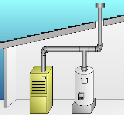 vent since it serves multiple appliances. And if the common vent needs to have a lower lateral section, that lateral section of the vent becomes known as a manifold.
Vent connectors are short runs of pipe, and there are many restrictions on where they can be installed. Vent connectors may not be installed in an enclosed location (such as within an enclosed wall), and they may not pass through walls, floors, ceilings and roofs. These restrictions do not apply to vent connectors made from a vent capable material such as a Type B vent pipe.
If the vent and connectors are not properly designed, acidic condensate from the vent gas can easily form on the inside of the vent pipe and cause rusting and pitting. As the corrosion process continues, the vent pipe becomes riddled with holes and ultimately fails. This same condensate can wreak havoc on masonry chimneys as well. Whenever this happens, a chimney could collapse or combustion gas containing carbon monoxide and all the other products of combustion can leak into occupied areas of the building.
Low efficiency gas appliances such as old 78 percent AFUE furnaces rarely have a condensate problem because the combustion gas exits with a relatively high temperature, making condensation difficult to occur. However, many furnaces and heaters have an efficiency above 78% and just below 83% with combustion gases that exit much cooler. These are known as Category 1 gas appliances that are non-condensing, and operate with negative pressure in their vent. These appliances are not designed as condensing type appliances, but they are prone to producing unwanted condensate if they are connected to improperly sized vents and connectors. Because of the many dangers related to acidic condensate, the sizing of vents and connectors is extremely critical for Category 1 type gas appliances.
Besides Category 1 appliances, there are Category II, III, and IV appliances. Category II appliances are no longer made, but some are still in operation. These are appliances that operate with a negative vent static pressure and with a vent gas temperature that may cause excessive condensate in the vent.
Category III appliances operate with a positive vent static pressure and with a vent gas temperature that usually avoids excessive condensate production in the vent. These appliances are direct sidewall vented without any additional apparatus. Positive pressure in the vent requires joints in the vent system to be sealed. Because these are 80 percent efficient sidewall vented appliances with combustion gases close to the dew point temperature, corrosion resistant materials must be used for the vent. And because condensate is possible, drains are typically incorporated to remove condensation before it can enter the heat exchanger. Category III appliances are typically used to solve installation problems where a vertical vent is not available.
Category IV appliances operate with a positive vent static pressure and with a vent gas temperature that causes excessive condensate production in the vent. Same as with positive pressure Category III appliances, Category IV appliances must also have all joints sealed in the vent system. Category IV is intended to cover 90 percent-plus efficient appliances. Category IV appliances are designed to dispose of combustion gas condensate as well as condensate formed within the secondary heat exchanger of the appliance.
Unlike with Category I appliances, there is no standard vent design procedure for Category II, III, and IV appliances. Every manufacturer of these type of appliances has to design a custom vent system specific to each model. Installers simply have to follow the manufacturer directions for these type appliances.
For Category I appliances, there is a standard vent and connector design procedure. This procedure is in the International Fuel Gas Code, which is published by the International Code Council. Many in the industry refer to this procedure as the "vent tables." In addition, you will often find these vent tables reproduced in the literature of many manufacturers that produce venting products.
Many factors affect the required vent and connector sizes for gas appliances. The appliance input Btuh rating, outlet diameter of the appliance, number of elbows, single or multi-story application, vent gas temperature, ambient air temperature, vent wall conductivity, vent connector type, vent thermal mass, vent pressurization (fan assisted or natural draft), vent height, and vent lateral length all affect vent design. The IFGC manual provides a whole array of vent tables that take all these factors into account so that both minimum and maximum allowable vent and connector sizes can be specified for any given situation.
Vents oversized and undersized cause problems. Undersized vents cause too much restriction for the amount of gases being released, and thus a proper draft may not be established to keep the gases moving upwards. If the undersizing is severe enough, a backdraft can occur such that combustion gases could reach occupied spaces with disastrous results.
Oversized vents cause numerous problems as well. The main problem with oversized vents is that the combustion gas can become too cool, as the velocity of the gas is slow in large vents. A low exhaust velocity allows the gases to cool, and condensate begins to form. A Category 1 appliance needs the combustion gases to stay above the dew point, typically 136 F for natural gas exhaust, in order for acidic condensation not to occur. Large masonry chimneys also make keeping the gases above this temperature very difficult, and that’s why flexible liners for chimneys are frequently needed for Category 1 appliances. See more on chimney venting issues here.
The first step in designing a Category I vent system entails selecting the vent and vent connector material types. The vent connector is the pipe that connects the appliance to the vent. A vent connector can be either single-wall metal pipe, or Type B, which is double-wall metal pipe with an insulating effect. The vent can never be made of single-wall metal pipe. It must be either Type B pipe, tile lined masonry chimney, or a flexible metal liner within a chimney.
Selection of single-wall metal or Type B vent connectors is mainly governed by cost and applicable restrictions. Single-wall metal vent connectors are lower in cost than Type B connectors, but they operate at much higher surface temperatures than do Type B connectors. Consequently, there are many restrictions on the use of single-wall metal pipe connectors.
For example, single-wall metal connectors cannot be used in attics due to the fire hazard, and they must have greater clearances on all structural components than Type B connectors. A good strategy for maximum safety and minimum chance of violating building code requirements is to use only Type B double-wall metal vent connectors.
If a chimney is not being used for the vent, the IFGC specifies that only Type B pipe can be used for the vent. If a chimney is involved, it must have an appropriately sized tile liner or a flexible metal liner. If a tile liner is used, it must extend the entire length of the chimney. Beware of chimneys that only have a tile liner at the very top.
Venting combustion gases through a chimney without a proper liner can result in the collapse of the chimney, as condensate can dissolve the mortar between bricks. Even if a tile liner is in place along the entire interior of the chimney, it is also possible that it may be too large for the appliances being vented through it. If there is any doubt as to the presence, size, and quality of a tile liner in a chimney, a flexible metal liner of the appropriate size should be used.
Once the vent connector and vent types are decided on, the proper sizes can be read from the IFGC vent tables. In the simplest case with only a single appliance, the information needed to size the connector and vent includes whether the appliance venting is fan assisted or natural draft, the appliance input Btuh rating, appliance outlet diameter, lateral distance from the appliance to the vent, height from the appliance to the top of the vent, and the number of 90 degree elbows used. For the given data, the vent tables list the minimum and maximum size vent and connector diameters that can be used.
Sizes from the vent tables can be easily read in a straight forward fashion. However, the size from the table must often be adjusted according to over 30 notes and exceptions explained in the IFGC manual. For example, for every 90 degree elbow beyond the quantity two, the Btuh capacity for a vent size must be reduced by 10%. Similarly, there are maximum horizontal connector length limits. The Btuh capacity of a vent must be reduced 10% for each multiple of a specified horizontal connector length.
There are many more such qualifiers on using the vent tables, and making sure all of them are honored is the main difficulty of vent sizing. It is not uncommon for a vent design to need three or more adjusting factors. This is particularly true for multiple appliance and multi-story applications.
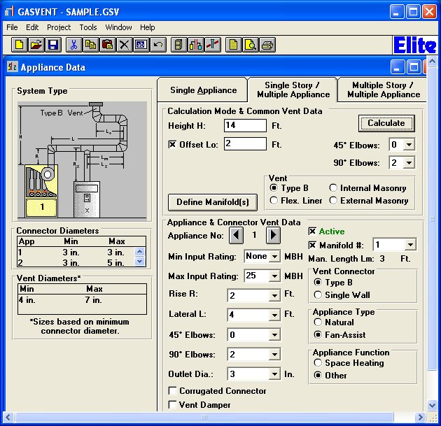
Fortunately, the table look-up values and all the adjustments for special conditions have been computerized. Elite Software has created the only computer program on the market today for this purpose, and it is called GasVent. Sizing vents is fast and easy with the GasVent software. A designer can quickly enter the information and instantly see the minimum and maximum allowable vent sizes, with all the checks and adjustments automatically done.
GasVent is very graphic and visually intuitive with detailed help provided for every input item. As can be seen in the sample GasVent screen, all of the required input dimensions are clearly labeled so it is easy to know what to enter. Calculation results are instantly displayed on the same screen.
There is no question that gas vent sizing can be quite technical and tedious to perform. While software can't remove all the risks in vent design and installation, it can definitely help you do more accurate designs in much less time.
Article updated 10/29/2018
