Overview
The Elite Software GasVent program quickly calculates the correct vent and connector sizes for Category I gas fired appliances. Category I furnaces, water heaters, boilers, etc. are mid efficiency appliances (up to 83%) that are quite common. If a vent for such an appliance is either oversized, undersized, or of the wrong material, there is a high probability that corrosive condensate from the combustion gases will either cause pitting of a metal vent or dissolve mortar if the vent is a chimney. There is not only property damage from such a failure, but also a life safety issue because the building occupants could be subjected to carbon monoxide. Besides gas poisoning, masonry chimneys can collapse from the acid in the condensate and possibly cause a fire. There are many potential problems with incorrect venting, and all contractors should make every effort to do the job right. GasVent is a great help in vent design, and is very graphical and easy to use.
Calculation Method
The calculation method used by GasVent is in the National Fuel Gas Code published by NFPA and International Fuel Gas Code which is published by the International Code Council. Many in the industry refer to this procedure as the “vent tables.” You will often find these vent tables reproduced in the literature of many manufacturers that produce venting products. These vent tables only apply to Category I appliances which are not designed for condensing combustion gases, and operate with negative pressure in their vent. Category II, III, and IV appliances require custom vent designs for each model from each manufacturer and as such, there is no standard vent design procedure for them.
In general, the vent tables for Category I appliances are fairly straight forward to use. However, there are many notes and exceptions that must be applied. For example, for every 90 degree elbow beyond the quantity two, the Btuh capacity for a vent size must be reduced by 10%. Similarly, there are maximum horizontal connector length limits. The Btuh capacity of a vent must be reduced 10% for each multiple of a specified horizontal connector length.
There are many more such qualifiers on using the vent tables, and making sure all of them are honored is the main difficulty of vent sizing. It is not uncommon for a vent design to need three or more adjusting factors. This is particularly true for multiple appliance and multi-story applications. This is where software like GasVent really helps out. See more about vent sizing here.
Program Input
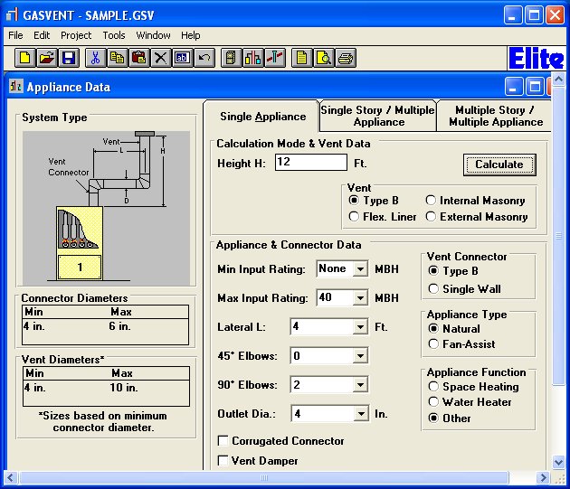
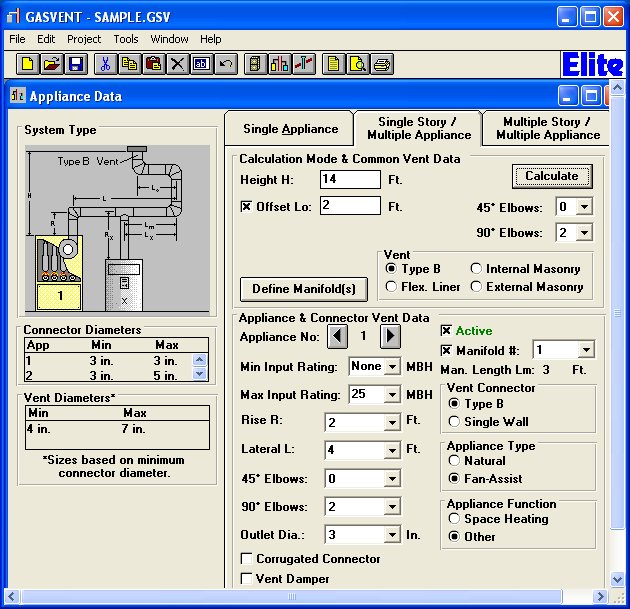
The GasVent program uses standard Windows data entry techniques that provide a simple "fill in the blank" input procedure. Since the terminology involved in vent design can be quite esoteric and difficult to envision, GasVent provides numerous graphics to help with this. For example, what is the difference between the lateral portion of a vent and a manifold? Or how about the difference between the lateral and rise length of a vent connector? To make these things easy to understand, GasVent uses context sensitive diagrams to illustrate the information it is requesting. See the example input screens below.
Three major types of data are requested for a GasVent project: Customer Information, Single Appliance Data, and Multiple Appliance Data if present. The customer information includes the customer name, address, city, state, and phone number. The information needed for a single appliance design includes the appliance function (water heater, space heating, etc.), input MBH rating(s), vent lateral and height dimensions, outlet diameter, vent connector type, specification of natural or fan assisted draft, vent type (masonry, flexible liner, or Type B), the number of elbows, and the presence of a vent damper. Only standard connector sizes are allowed.
The same data is requested for each appliance in multiple appliance situations plus there is additional information concerning manifolds. Multiple appliance scenarios also allow the entry of a "floor" number for multi story buildings.
Program Output
Once all the necessary input data is given, GasVent displays the minimum and maximum vent and connector sizes underneath the vent scenario diagram of the input screens. See the example input screens below. Formal printed reports are also selectable. These reports include all the input data as well as all details concerning each venting case. A combustion air report is available as well. To see sample reports, click here.