Features
- Draws HVAC Air Flow and Hydronic Schematics
- Allows Unlimited System Arrangements
- Hundreds of Component Makes Are Provided
- Schedules Can be English, Metric or both unit systems
- Intelligent Components Communicate with Each Other
- Supports Water, Propylene Glycol, Ethylene Glycol, & Steam
- A dual season Imposed Load component for modeling change-over systems
- Multiple Imposed Load graphic types for modeling varied hydronic systems
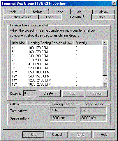
- Creates Schedules for All Types of Equipment
- Schedules Can be DXF Files or Spreadsheet Files
- Taco LoadMatch® single pipe system automated design feature
- Calculates Boiler Flue Sizes
- Includes Air and Fluid PropertyCalculator
- Includes Fan and Pump Law Analyzer
- New! Links with Chvac and Rhvac
Overview
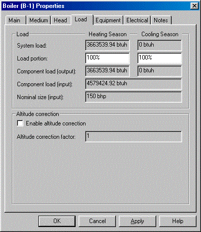
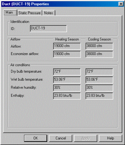
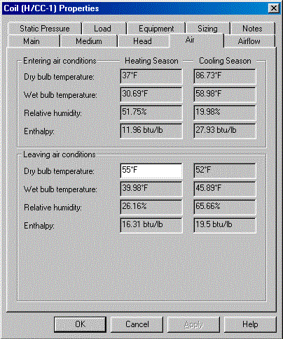
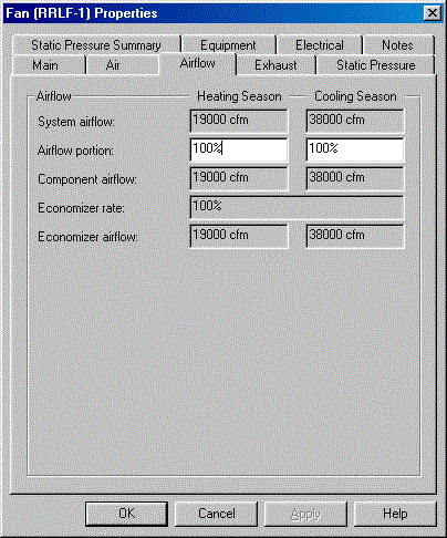
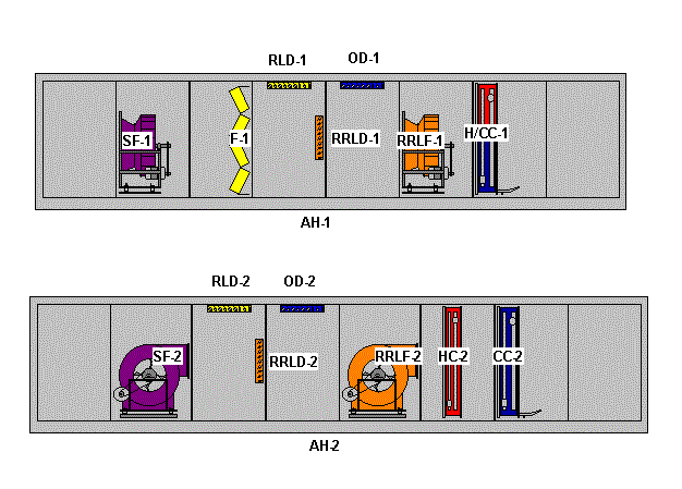
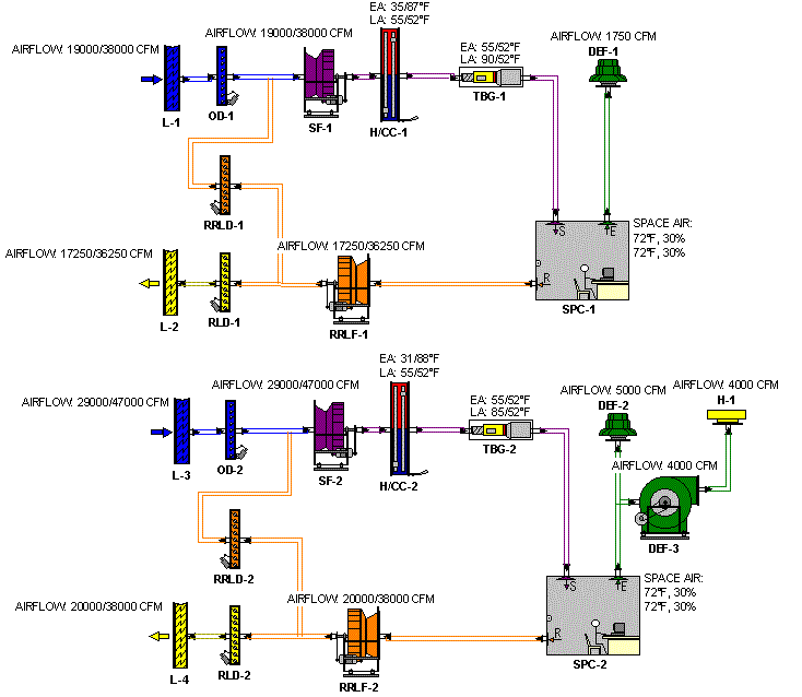
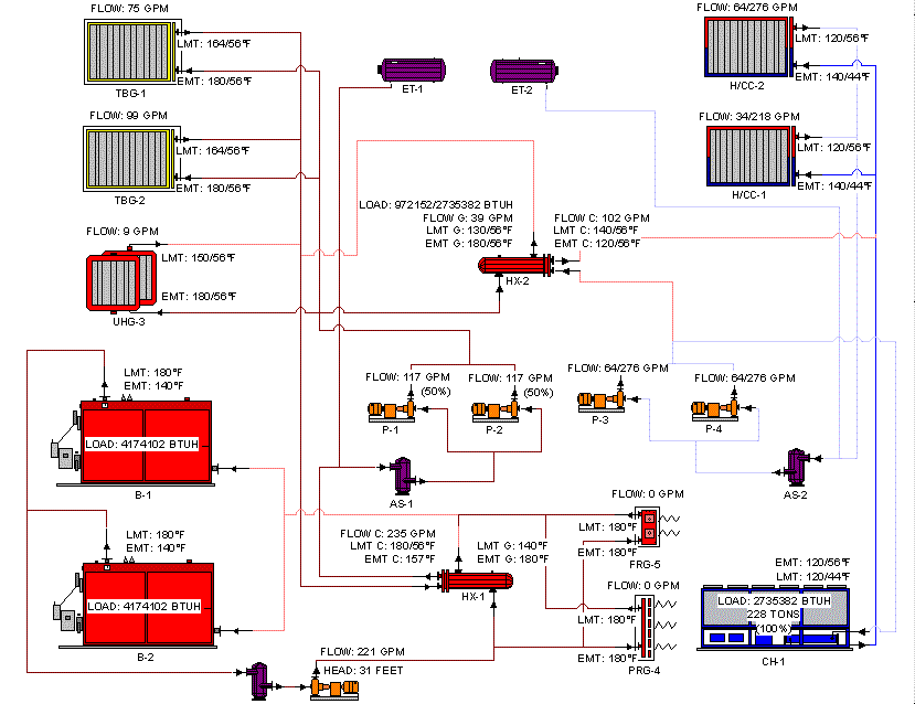
HVAC Solution is a schematic diagramming and database tool for laying out the equipment involved in an hvac system. It is the only program of its kind in the world. A complex hvac system often involves one or more chillers, boilers, cooling towers, numerous air handlers, fans, coils, pumps and more. All of these air flow and hydronic items have to be carefully selected and coordinated with one another. HVAC Solution lets you drag detailed icons of these components and place them on the page and then connect them with schematic pipe lines. Each of the components contains performance and sizing data that is maintained with the component.
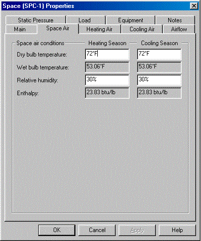
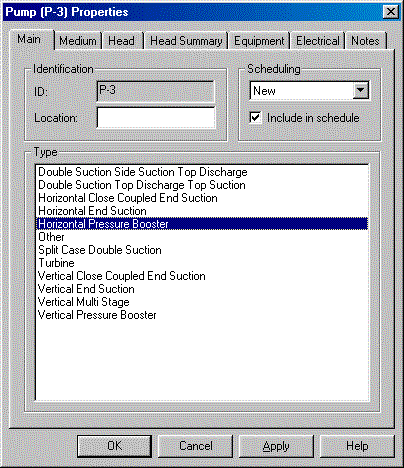
More than just drawing pretty pictures, HVAC Solution is also an intelligent database. All pertinent data can be entered and maintained through pop-up forms for every component in the system. Once connected together, each component automatically communicates information back and forth to the other components. This allows the software to guide the designer on making sure the components are matched up and coordinated correctly. As the system diagram and database is being built, all the data is being updated and saved for quick retrieval or sharing with other applications.
The end result is that you have full color presentation quality hydronic and airflow schematics as well as equipment schedules for construction documents and drawings.
Chvac and HVAC Solution Link
The Chvac load calc program calculates a great deal of the data needed to define a system in the HVAC Solution schematic diagramming program. Traditionally, this data has simply been transferred using a manual entry process. Now, there is an automated process whereby HVAC Solution can import all the relevant Chvac data system by system into the HVAC Solution software such that HVAC schematic diagrams are automatically generated. See a video demo of this process here and view more details on Chvac here.
Program Input
HVAC Solution has beautiful detailed icons for all these types of components: air handlers, supply fans, return fans, return-relief fans, relief fans, outside air fans, exhaust fans, pumps, hydronic boilers, air cooled chillers, water cooled chillers, expansion tanks, air separators, cooling towers, heat exchangers, cooling tower sumps, dampers, heating coils, cooling coils, roof hoods, louvers, terminal boxes, panel radiation, finned radiation, unit heaters, and fan coils. Using HVAC Solution involves the following steps:
- Drag and drop components onto the page.
- Enter specific component information at each component.
- Connect components in schematic form to define component relationships.
- Review the automatically generated schedules for each type of equipment.
- Save the project for later retrieval.
Program Output
Besides the air flow and hydronic schematics that can be previewed or printed, HVAC Solutions also produces numerous equipment schedules. Just some of the schedules available include: boilers, chillers, air handlers, air separators, coils, cooling towers and dampers. These schedules are provided as both DXF files and spreadsheet files. This makes it easy to just print the schedules, import them directly into drawings and other documents, or manipulate the data further in a spreadsheet.